Intro to 4 Basic Computational Design Typologies
This is a continuation of a previous post called “What is Parametric Design?,” which aims to demystify computational design and digital fabrication. In this post, we will break down the 4 most common parametric design typologies that are prevalent in forming the building blocks for many projects. This article is meant as a basic introduction of common computational design typologies, typically created within the Grasshopper plugin for Rhinoceros.
1) The Waffle
Waffles are ubiquitous in parametric design, and for good reason: they allow a designer to quickly build small and large forms that are inherently structural. The premise is this: you have fins in two directions, which interlock with each other. These joints are achieved by notching the pieces then sliding them together; these joints can be glued and clamped together for a stronger connection.
The waffle can either be scripted manually, or can be created through a grasshopper plugin called bowerbird. I would recommend learning how to manually script a waffle to understand how this system is created.

Metropol Parasol / Jürgen Mayer H.

Restaurant Hallway / Studio Robazzo
2) Wood Fins
Here at Robazzo, we make a lot of wood fin walls. They provide a very elegant wall finish to complete a project, and, like the waffle, allow for the expression of organic forms in a quick way. The process is based on accentuating either the horizontal or vertical fins in a waffle, and either limiting or omitting the perpendicular fins. This allows you to increase the density of the fins, further accentuating the organic form you have modelled.
If omitting the perpendiculars all together, then you will need to devise a method to construct your system. If on the wall, how are you attaching them to the wall? If free-standing (like a screen) how are they going to stand up? That is up to you to figure out and should be considered carefully.
3) Perforation
Perforation is more of a meta-group, as each type is different, but they all have one central thing in common- they’re all made by cutting holes into a surface. The first step of any perforation pattern is to compose a grid system which subdivides a surface. This grid creates points to act as anchors for any shape, which can then be modified parametrically.
Perforations can be classified into several categories (we are omitting shapes that have no parametric quality ie. no change in shape):

Bukit Pantai Residence / OOZN

3a) Gradients
Gradient patterns are based on attractors and detractors in the form of a point or curve which is pulling or pushing information. A distance factor is critical, as we can quickly measure from each grid point to our affecting geometry. We set up our script to be such that this change in information is modulating the shape, size, and cull parameters. Remember to keep your data separated into properly organized tree branches so each shape can be processed individually. At Robazzo, we typically remap our distance numbers. You can do this by constructing a domain of your highest and lowest numbers, then re-mapping them to be within a domain of 0.2 - 0.9. We do this to utilize the uniform scale function.

3b) Voronoi Patterns
Voronoi patterns can be seen throughout nature, like on the wings of a dragonfly or in the way that plant cells come together, and have a very distinct & organic look to them. To make a voronoi, you can either use a standard grid like in the previous example, or you can opt for a more “random” appearance which invokes a more organic and natural appearance.
Poptograf / Studio Robazzo
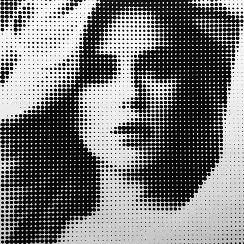
3c) Image Sampling
When you want to use an image to inform your perforations, you need to add several steps to your script. There is a good workflow here at Robazzo that I will share:
Define the size of your piece (x & y) in millimetres.
In Photoshop, take your image and crop how you would like the image to look.
Resize your image (in pixels) to the x and y mm size of your piece. In this case we are defining 1px = 1mm. This makes it easy to work with in grasshopper.
Greyscale the image.
You’re ready for grasshopper!
Now, you will need the same grid setup on your surface, and these points are then plugged into an image sampler. In the image sampler, load your selected image then switch to use the greyscale information from the image. This will output a value of 0-255 that is associated with a grid point. Now remap these numbers (same with the gradient) and you have a method to scale your shapes to match the image.
4) Tessellation
Triangles and hexagons are the two main primary methods of tessellation, and for good reason: they fit together seamlessly. How this is achieved is through a grid network that is applied to a surface then broken down into “cells”. They can be structural if the appropriate steps are taken to ensure the panels can connect together, or alternatively they can act as a skin which is applied over another system. The most important thing when working on a tessellated surface is to ensure you are producing “planar” cells. If they are not planar you will have difficulty producing the panels when constructing your form physically.
A really great plugin for grasshopper is called Lunchbox. This tool expands grasshoppers ability to create different grids.
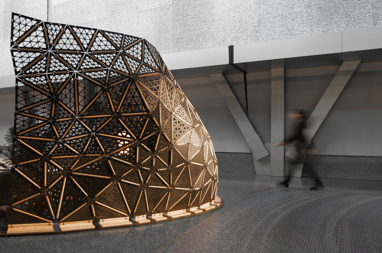
TED Partition Screen / Studio Robazzo
Want to learn more about parametric & computational design?
Click here to read our original post, “What is Parametric Design?”